Block Model Slice Display
A model is a small-scale representation of a real situation. Models are usually designed and made to be manipulated or processed in such a way as to enhance the understanding of the situation the model represents.
Block models represent three-dimensional shapes, volumes, tonnages and grades of solids such as ore zones, waste zones and other volumes of geological or mineralogical interest. Block models consist of blocks, which are cubes or cuboids, stacked together to fill the defined volume as closely as the block sizing criteria allows.

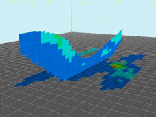
Example of two concurrent 3D window block model intersections
You can view a block model using many rendering options, as found on the Block Model Properties: General screen.
Block Model Quick Sections

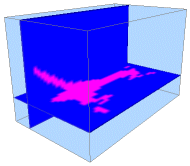
An example of a two concurrent block model quick sections
The Quick Section rendering option is an excellent method for analysing the contents of a block model.
It is also extremely useful when viewing seismic data as, once a quick section display type has been selected, you can use Quick Section Controls to sweep backwards and forwards throughout the model in any of the standard 3-dimensional planes (IJ, JK and IK - planar equivalents of X, Y and Z directions).
As the name implies, it is a rapidly-rendered view of the model as a slice, using the information known about the centroid of each model cell and interpolating that view to give an estimate of the model contents. It doesn't display cell boundaries accurately, but it does give a reasonable indication of the structure(s) the model contains, if viewing with an appropriate legend.
Note: you can't use the Quick Section Control toolbar with an Intersection display type (see below).
The Quick Section Controls can be accessed by right-clicking or tapping a model overlay (displayed as a quick section) in the Sheets or Project Data control bars.
-
Set the alignment of the section along a major axis using the IJ Plane, IK Plane or JK Plane buttons.
-
Use the slider to position the section forwards or backwards in an orthogonal direction.
Block Model Intersections
One of the distinguishing features between an Intersection and a Quick Section is that an Intersection display type relies on a previously defined 3D section being available.
An Intersection can also display sub-cells as well as parent cells (as opposed to Quick Sections, which can only display parent cells). In essence, the Intersection display type results in a more detailed display of model data.
The Intersection display option is used to show the plane created by the intersection of a loaded geological model and the selected section plane (remember that these section planes can be defined both interactively using the Sections folder in the Sheets or Project Data control bar (see Sections overview) or from loaded section definition files.
Whilst a 3D section represents a singular plane, a section table can contain any number of sections, with each being defined by a separate database table row. This single-multiple distinction is important, as explained below.
If a block model is rendered as an Intersection, the Block Model Properties screen (General tab) lets you choose an Intersection Section.
-
For all interactively-defined (single) sections, the name shown in the drop-down list is the same section name as shown in the Sections folder of the Sheets or Project Data control bar.
Selecting a section (and applying changes) displays the loaded block model as the intersection between the geological model and that section plane.
Changing the definition of a section object in memory (using the Section Properties screen) automatically updates the view of the block model intersection display associated with it - once a section is associated, you only have to change the definition of that section for the display of the model to update automatically.
-
If a section definition table is loaded, this is shown in the list as the name of the loaded section table object (it will have a "(table)" suffix). If selected, the geological model is shown as the intersection of the specified block model data with the currently active section definition.
The concept of an active definition is important, as you can swap between sections within the same file using that section object's context menu to access its properties.
Note: the Intersection display type does not support Quick Section Controls. This is only available for Quick Sections (see above).
To create multiple section displays of the same block model:
Each block model section display is relevant to a particular block model overlay.
As Studio products support multiple overlays per object, to create multiple sections, you create multiple overlays.
-
Load and display the block model to be viewed, using any formatting.
-
Using the Sheets or Project Data control bar, right click the default model overlay and select Properties (or double-click the model as displayed in any 3D window).
-
If not set already, change the Display Type to Quick Section or Intersection (whichever you prefer). See above for more information.
-
If displaying an Intersection, choose a section or section table from the Intersection Section list.
-
Click OK.
The model display updates to display the new rendering options.
-
If displaying a Quick Section:
-
Right click the block model overlay in the Sheets or Project Data control bar and choose Quick Section Controls.
-
Use the Section Control tool to position the quick section along one of the major axes.
-
Dismiss the Quick Section Controls tool.
-
-
Right-click the block model overlay again and select Copy.
A duplicate overlay appears.
-
Modify the section display of the duplicate overlay so it is different to the first:
-
To create an additional block model Intesection.
-
Double-click the model in a 3D view to display the Block Model Properties screen.
-
Ensure the Intersection Display Type is picked.
-
Select an item in the Intersection Section list. If you already have an Intersection displayed, make this one a different section.
-
Click OK.
-
The screen updates to show both block model sections.
-
-
To create an additional block model Quick Section:
-
Double-click the model in a 3D view to display the Block Model Properties screen.
-
Ensure the Quick Section Display Type is picked.
-
Click OK.
-
As previously, use the Quick Section Controls to position the section display.
-
Using this approach, you can have as many model sections as you need, and can even mix block model display types to include sections, points, blocks or lines.
-
Related topics and activities

